
Vestel 17ips62 Schematic
He went deeper. He followed the traces to a small, obscure component labeled R812 . It was a surface mount resistor, tiny as a grain of rice. The schematic said it should be 100k Ohms. It was part of the startup circuit for the PWM controller.
Essential for the TV to respond to remote control signals when "off". Core Components in the 17IPS62 Schematic vestel 17ips62 schematic
Here is what the provides:
The technician follows the lines on the schematic, using a multimeter to hunt for "missing" voltages. They might find a blown fuse (), a shorted diode ( D12 ), or a bulging capacitor. With a quick solder and a replacement part, the "dark" story ends with the screen flickering back to life. He went deeper
: Features line filters (LF2, LF4) and bridge rectifiers to handle raw AC input, producing a high-voltage DC rail (approximately +400V). The schematic said it should be 100k Ohms
Click here for more info.
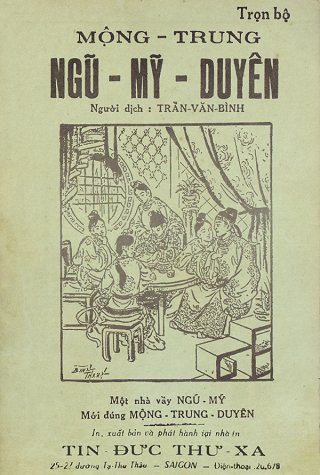
Mộng Trung Ngũ Mỹ Duyên
•
Trần Văn Bình

